Unboxing and Setting Up the Magni 6 Mini
This guide walks you through unboxing your Magni 6 Mini, inspecting it for damages, and getting it ready to drive.
What You’ll Achieve
By the end of this guide, you’ll have a working Magni 6 Mini robot that’s ready to connect, drive and explore.
Unboxing
The Magni 6 Mini arrives in a package like this:
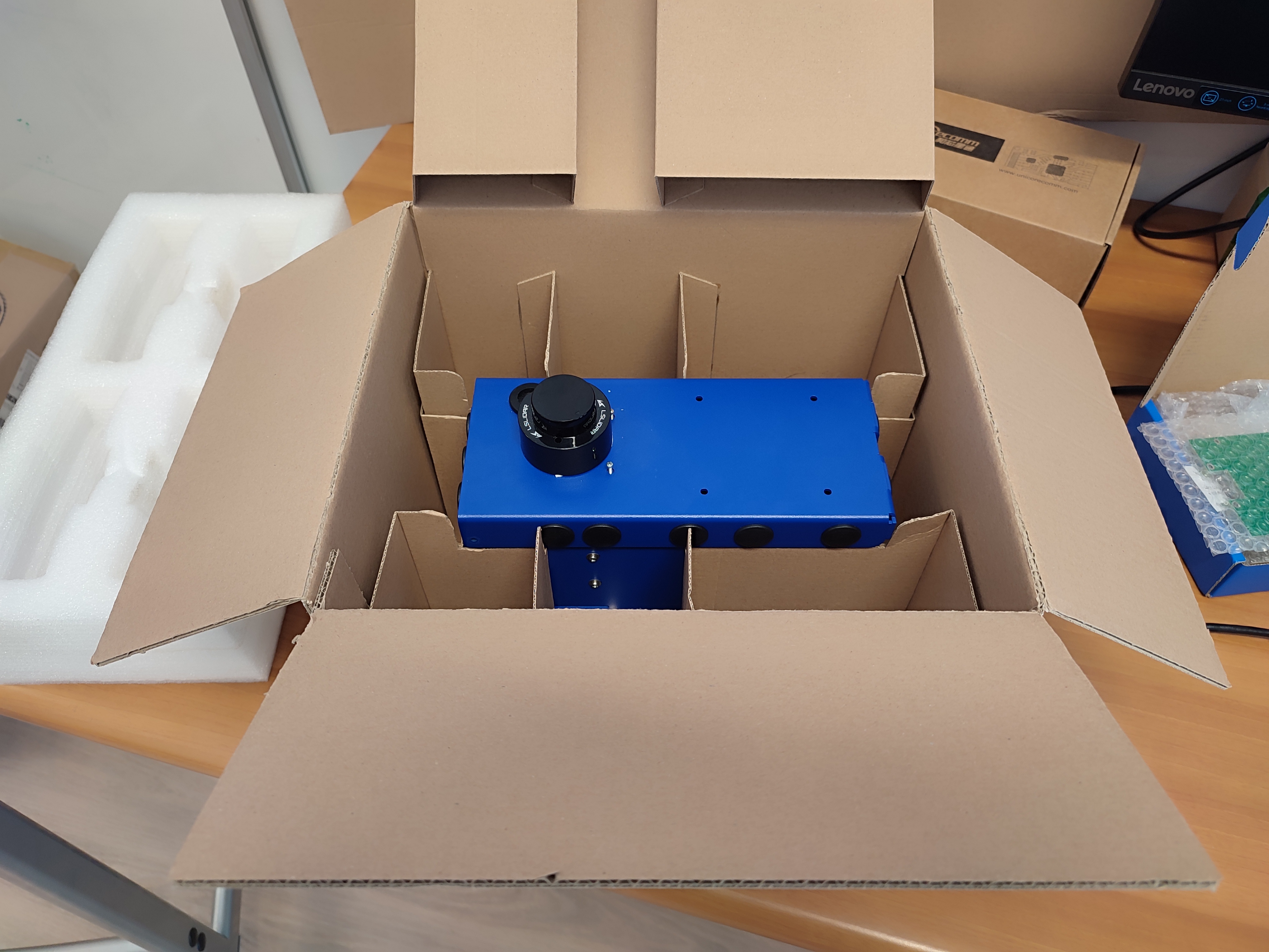
Package Contents
1x Magni 6 Mini Robot (pre-assembled)
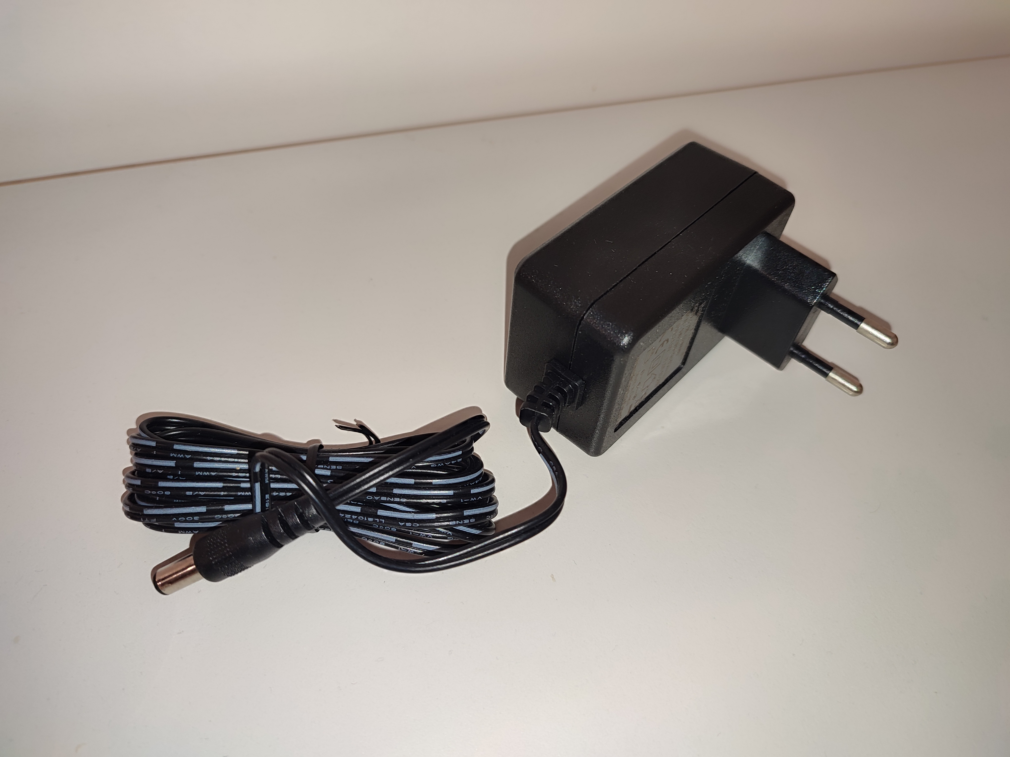
1x Battery Charger (See: Batteries on how to charge.)
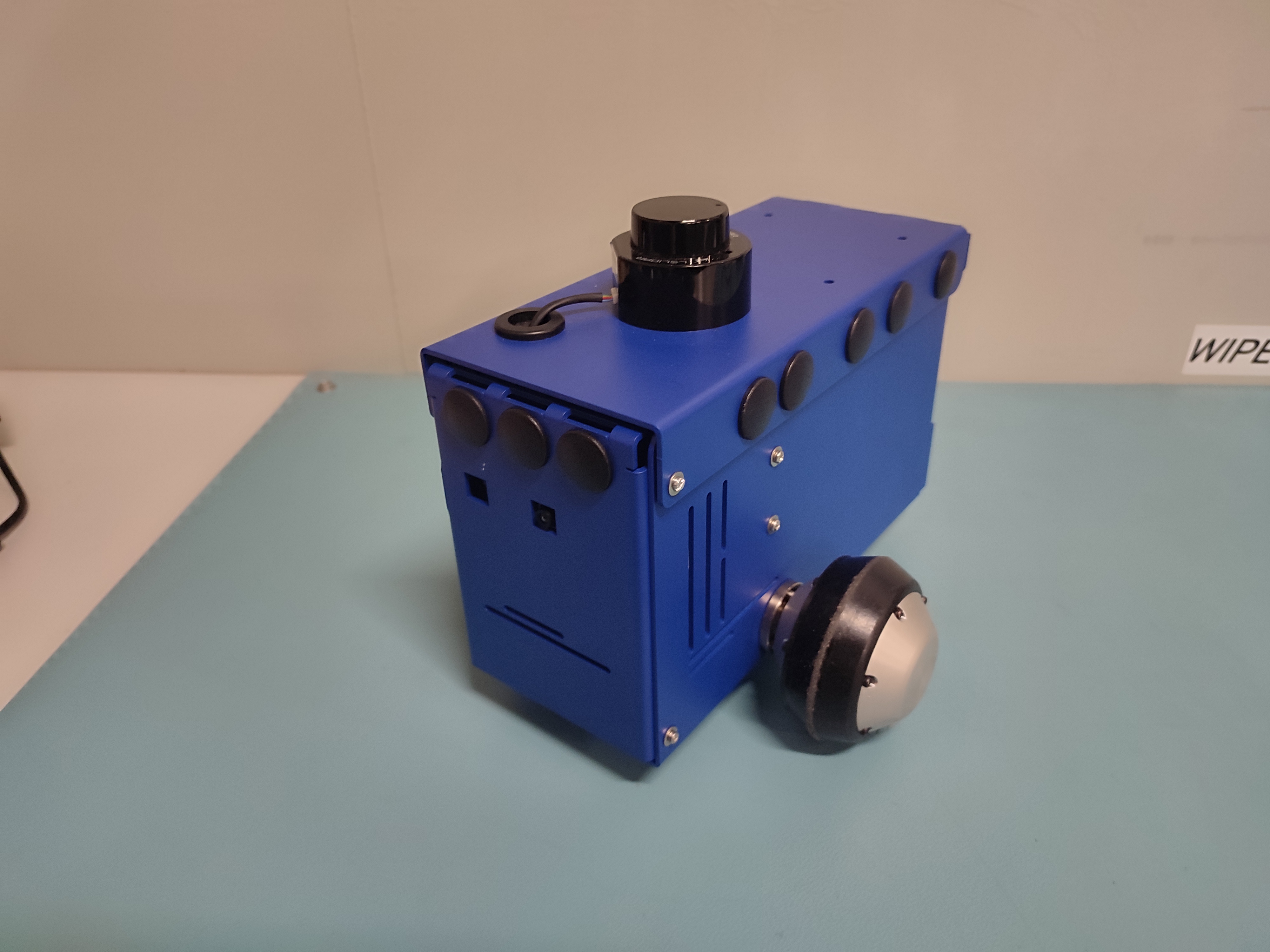
Initial Inspection
Before powering on, check all components are included and undamaged.
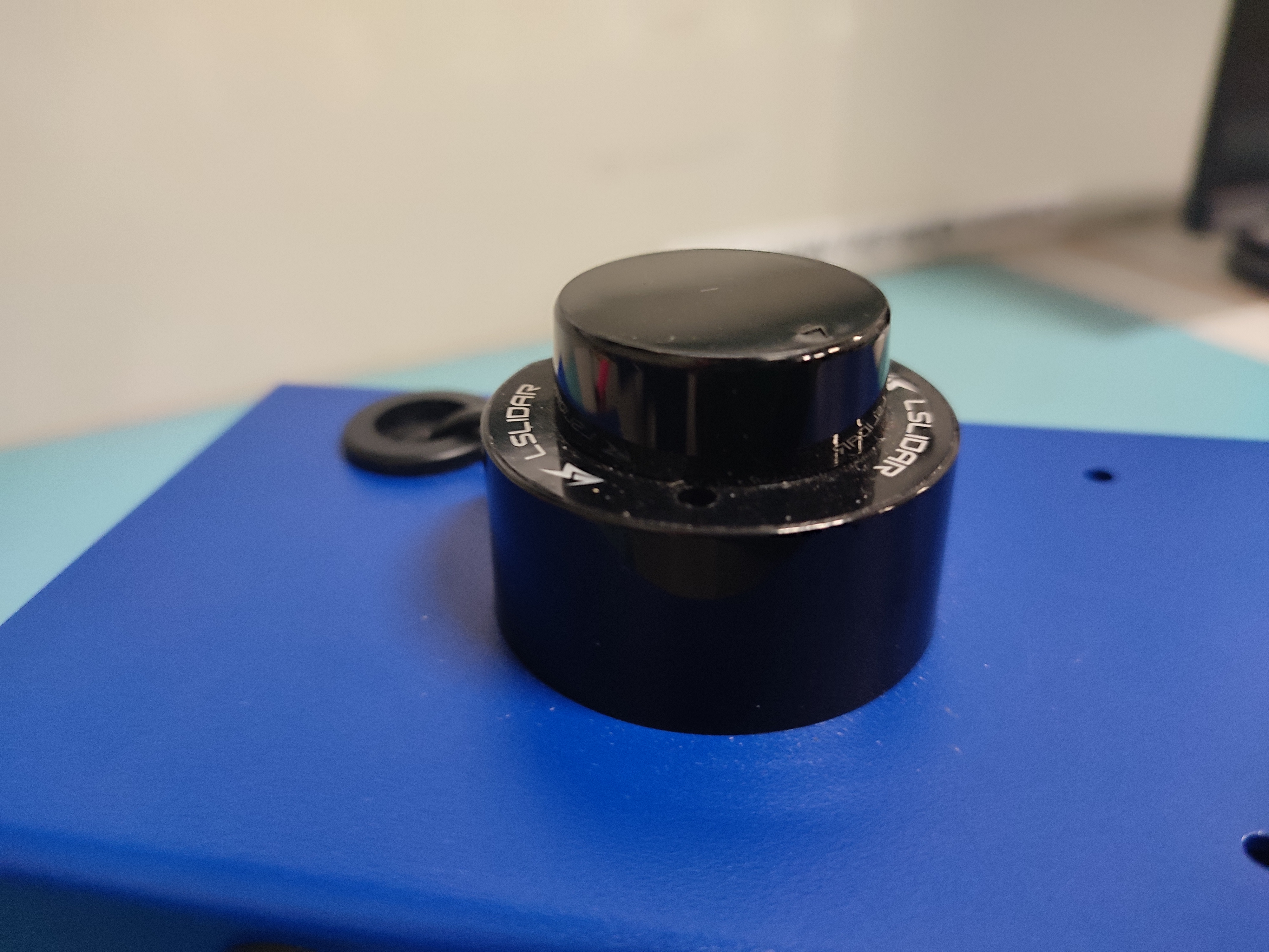
1. Exterior
Lidar
Chassis
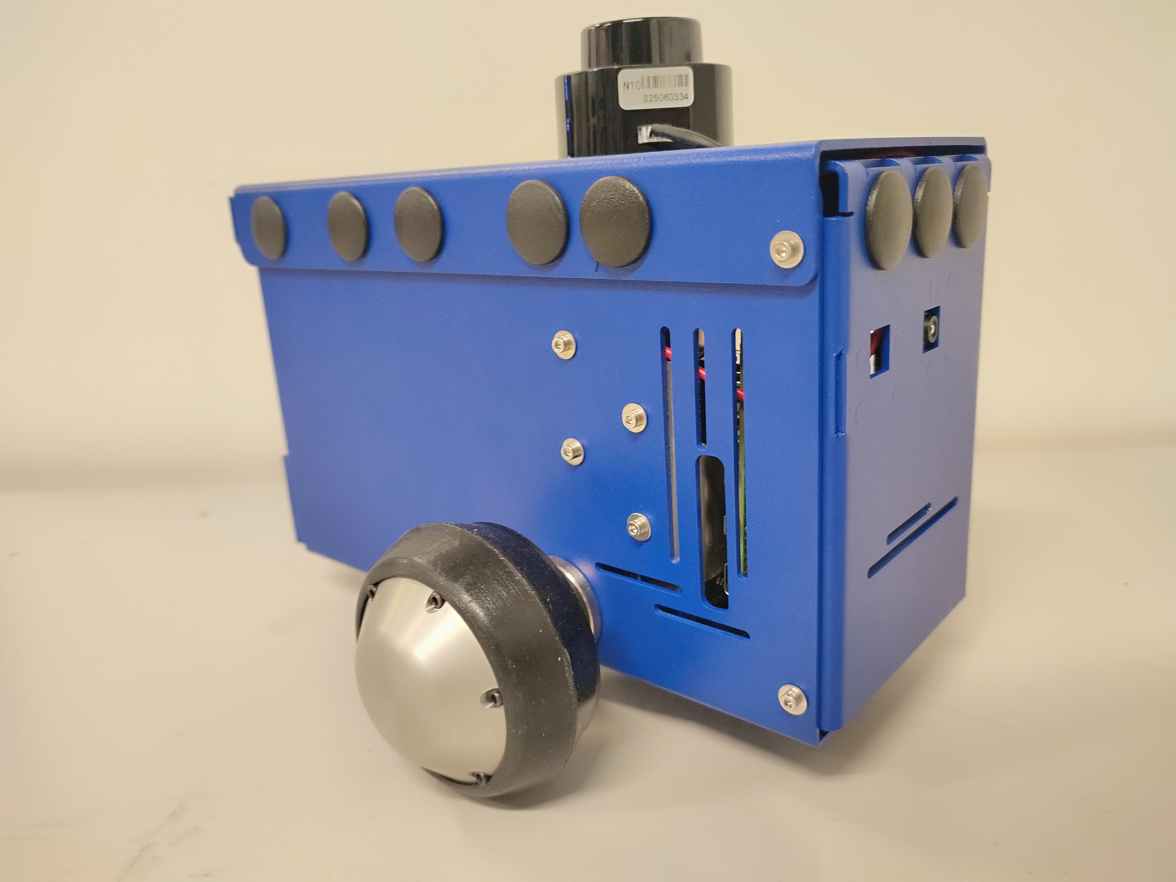
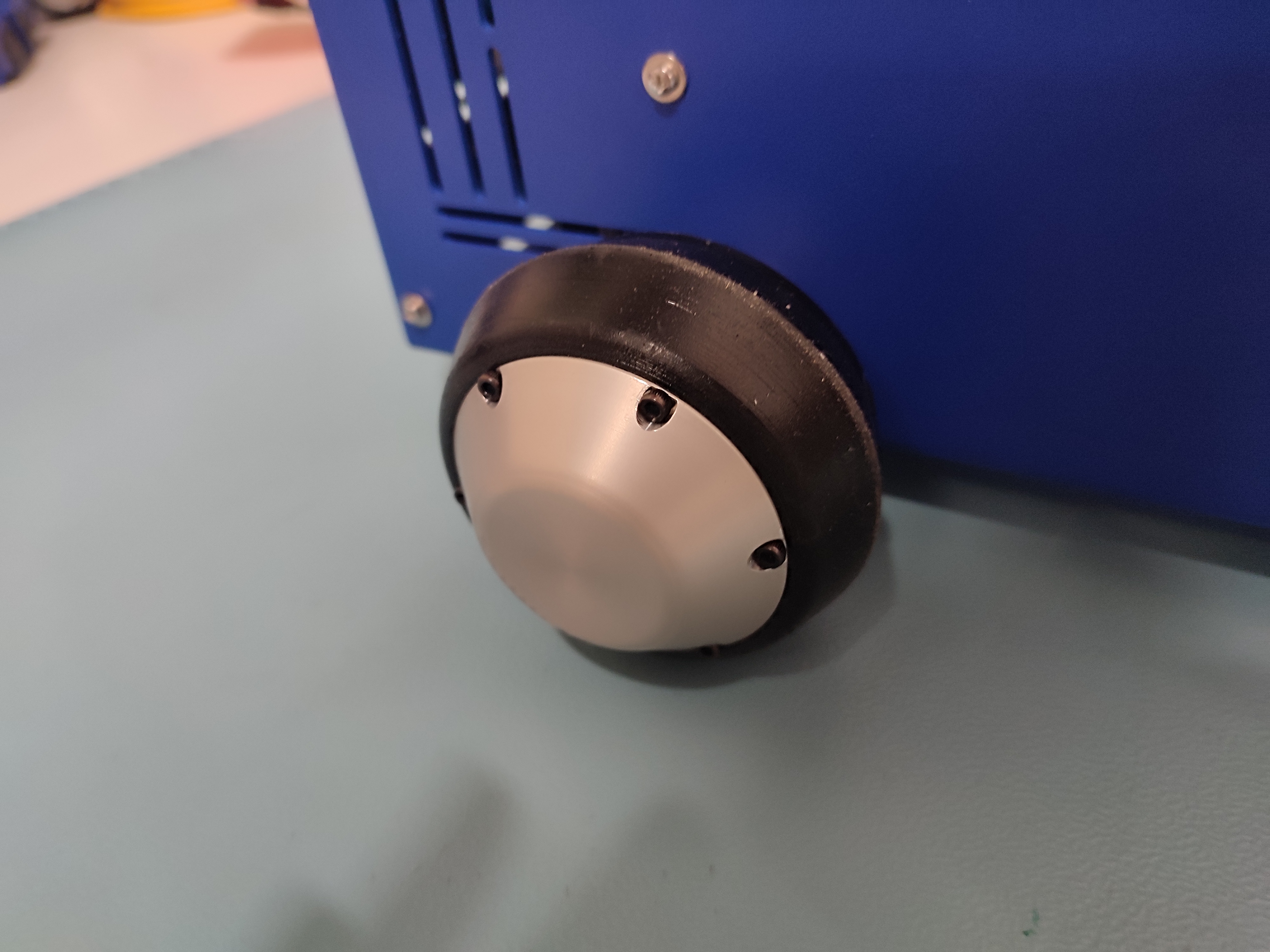
Motor Wheels
2. Interior
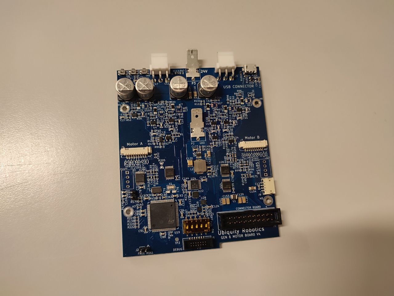
Motor Controller Board
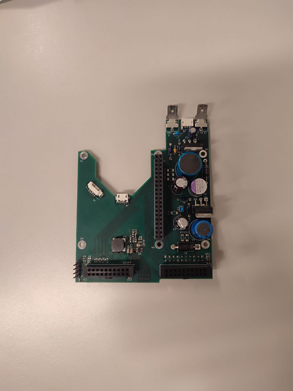
PCB Connector
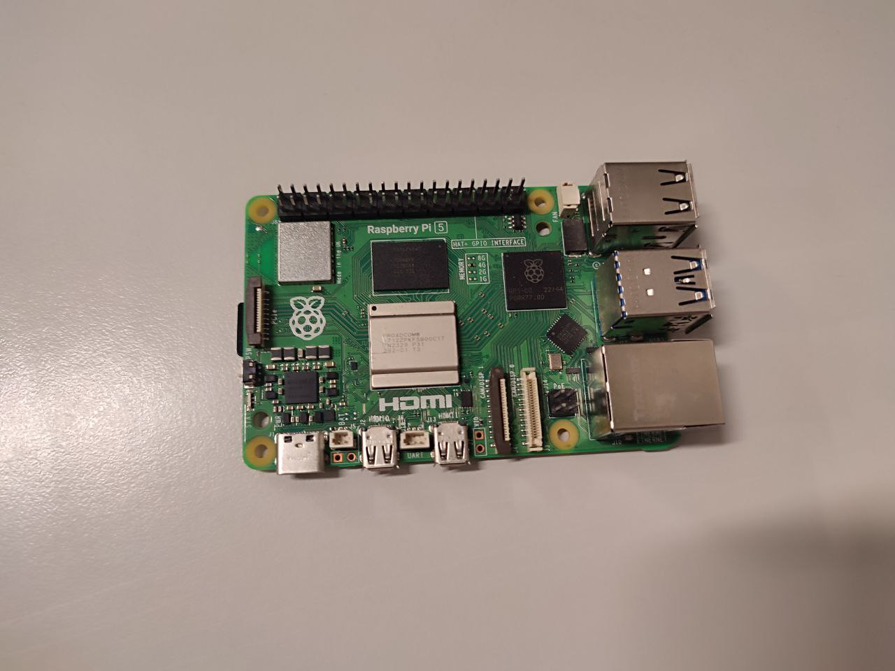
Raspberry Pi
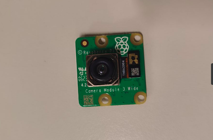
Pi Camera
All the necessary wires
3. Checklist
Ensure all pre-assembled components are firmly connected:
MCB connected to Raspberry Pi 5 via the PCB connector.
Motor wheels connected to MCB.
Look for loose connector, cables, or wheels.
Important
The robot is shipped pre-assembled, but verify all parts are secure.
If all components are securely connected and undamaged, proceed with adding the batteries in the robot.
Important
Upon receiving the package if any of the components:
Are missing,
Are not properly connected,
or are damaged,
contact us at Ubiquity Robotics support.
Battery Installation and Safety
The Magni 6 Mini uses two lead-acid batteries. Ensure the Magni 6 Mini’s these two batteries are safely installed and charged before powering on. For for exact instructions on how to charge the batteries before adding them to ther robot: Batteries.
Note
When ordering batteries, ensure they have 6.35mm (or 6.4mm) FASTON terminals. Some batteries come with smaller 4.75mm terminals, which are not compatible with the standard Magni wire harness.
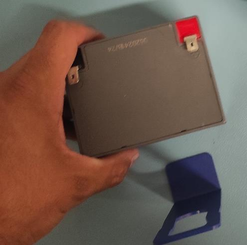
1. Inspect the Batteries
Look for visible damages (cracks, swellng, or leaks).
Do not use damaged batteries.
2. Install the Batteries
Place both batteries inside the chassis.
Connect them to the MCB, the switch, and to each other using the supplied cables.
Ensure the connection is firm to avoid power issues.
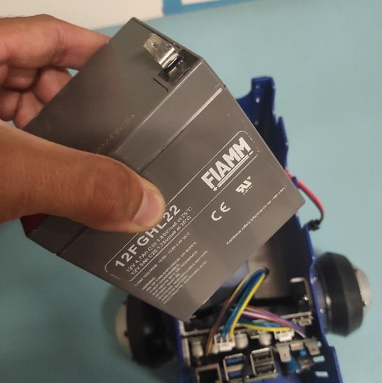
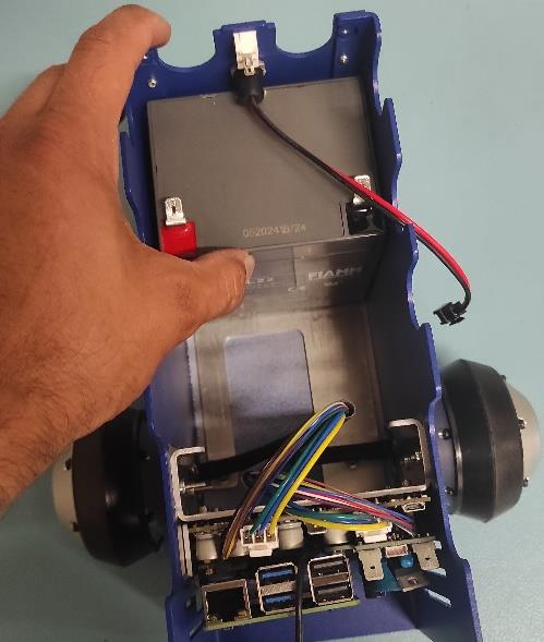
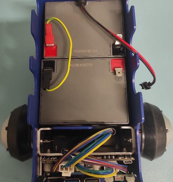
Install the First Battery
Position the first BATTERY in the BASE according to the pictures below. Pay close attention to its orientation.

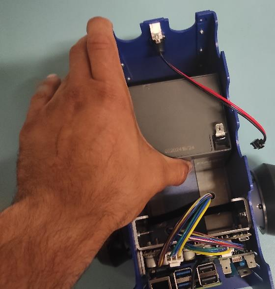
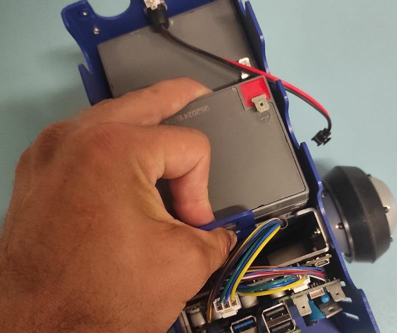
Install the Second Battery
Use the BATTERY HOLDER to secure the second BATTERY in the BASE as shown in the picture.
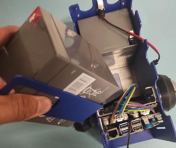
Properly Adding the Second Battery
Be careful with the wires.
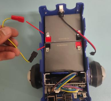
Connect the Batteries in Series
Attach the yellow-green wire: red connector to the RED spade of the first battery, black connector to the BLACK spade of the second battery.
Note
Red connector from the wire goes to the RED spade of the first battery. Black connector of the wire goes to the black spade of the second battery.
Connect Black Spade to Battery
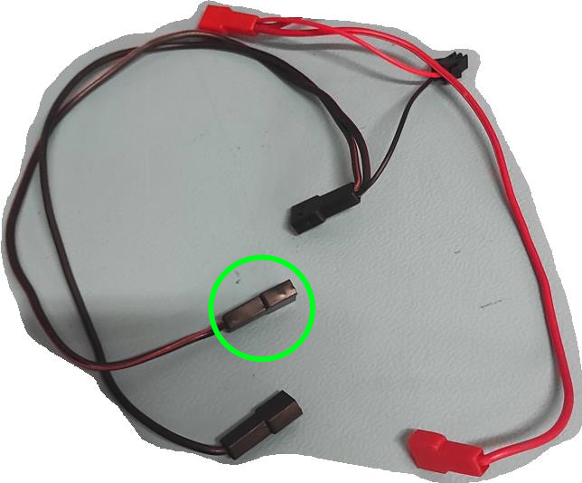
Take the wire harness and connect the black female spade terminal to the negative battery pin as shown in the picture. Press it in firmly.
Connect Black Spade to Ground
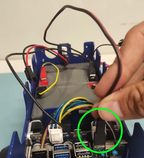
Grab the only free black female spade connector and attach it to the GND pin on the CONNECTOR BOARD as shown in the picture.
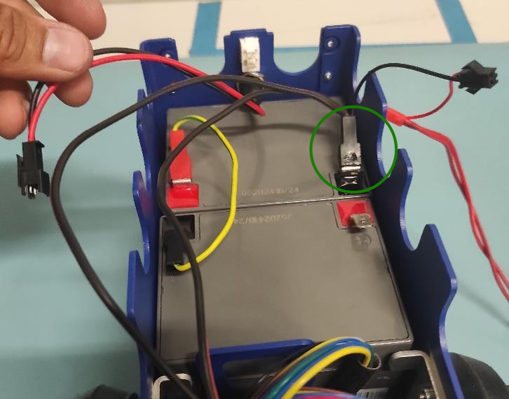
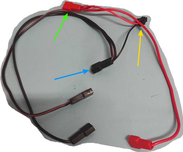
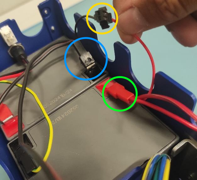
Connect Red Spade and Charger
Attach the short RED spade connector to the positive battery pin (green circle). Connect the charger connector to the 5.5 x 2.1 mm DC POWER CHARGER (yellow circle). Finally connect the BLACK spade connector to the negative spade of the first battery (blue circle).
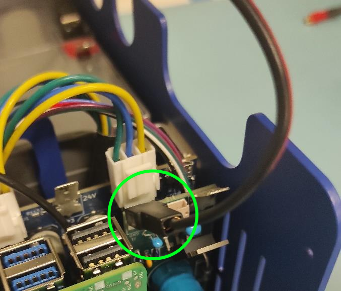
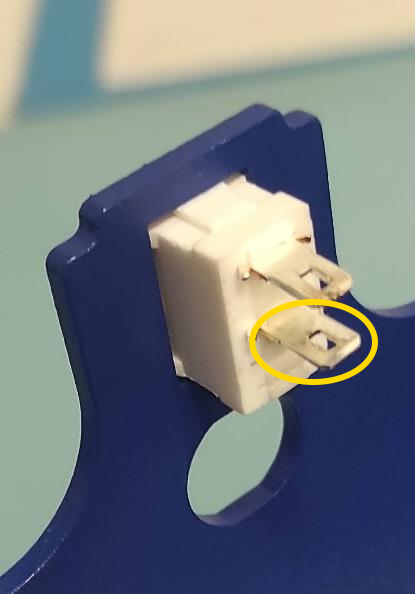
Connect Red Spade to Switch
Attach the remaining red spade connector to the upper pin of the ON/OFF switch.
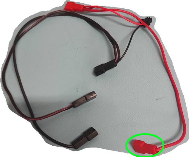
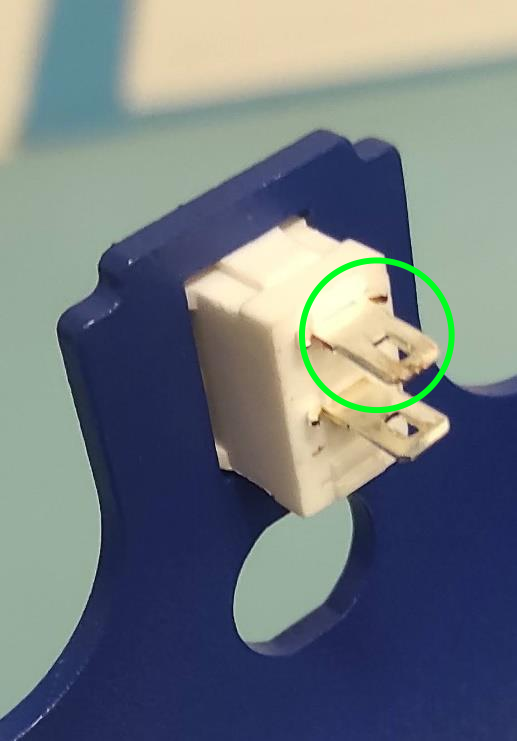
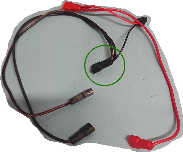
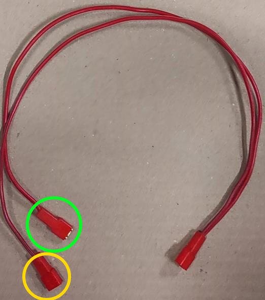
Connect Second Wire Harness
Use the wire harness with 3 red spade connectors. Attach the split connector (yellow circle) to the bottom pin of the ON/OFF SWITCH.
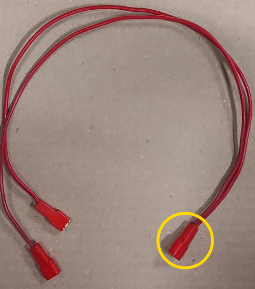
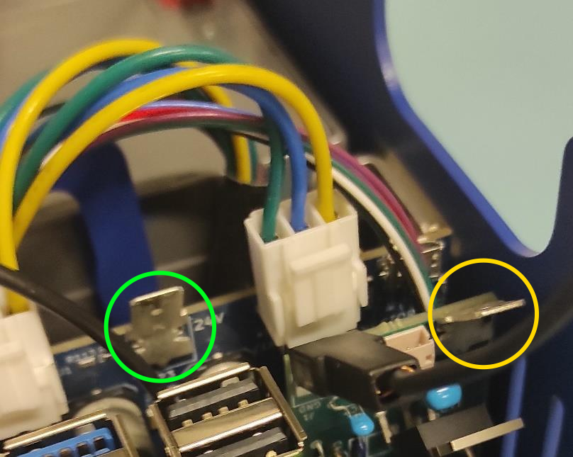
Connect Remaining Spade Connectors
Attach on red spade connector to the 12V pin on the CONNECTION BOARD and the other to the 12V pin on the MOTOR BOARD.
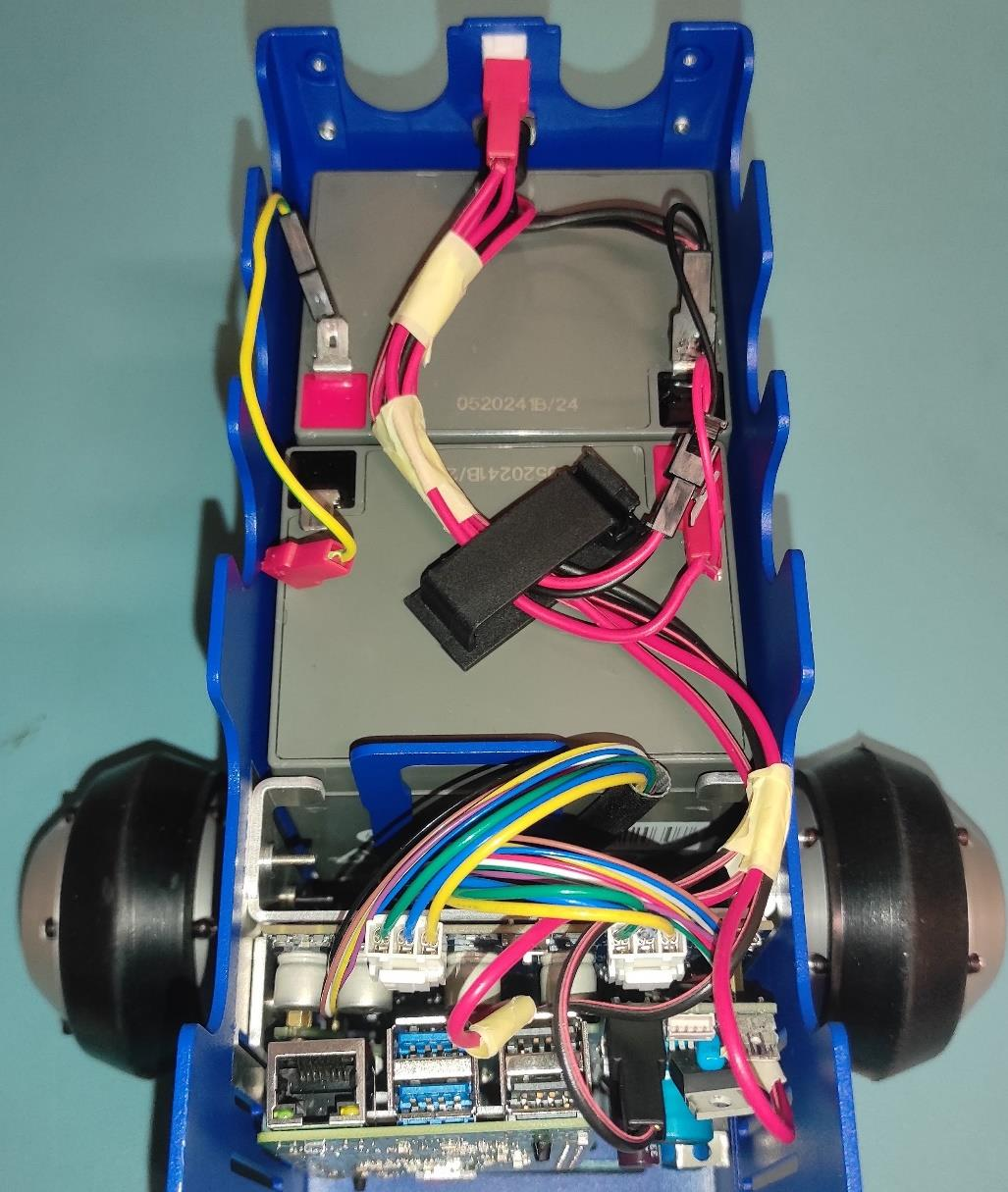
Verify the Wiring
Ensure all spade connectors are firmly attached. Route wires as shown.
Important
Double-check that all connections (all pins are firmly connected).
Note
UPDATE of the WIRE ROUTING is coming soon.
Warning
THE VOLTAGE CONNECTED TO THE MAIN CONTROL BOARD (MCB) MUST REMAIN 30.0V OR LESS AT ALL TIMES!
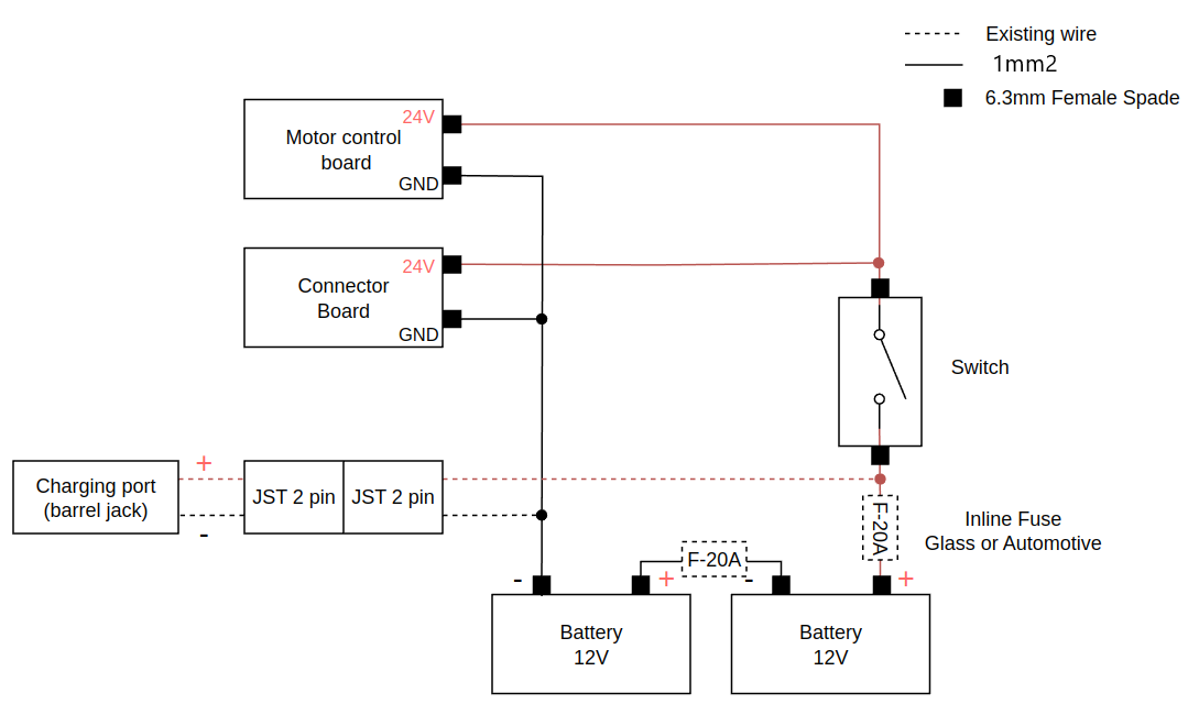
The wires should be connected like this:
3. Charging
Use a multimeter to confirm the voltage of the batteries.
Use fully charged batteries. If the batteries are installed in the robot, charge them using the provided charger. Otherwise, use a power supply. For detailed charging instructions, refer to the Charging Guide.
Warning
Do not use a damaged battery, as it may pose a safety hazard.
Charge in a well-ventilated area away from flammable materials.
See Batteries for more information.
Powering On
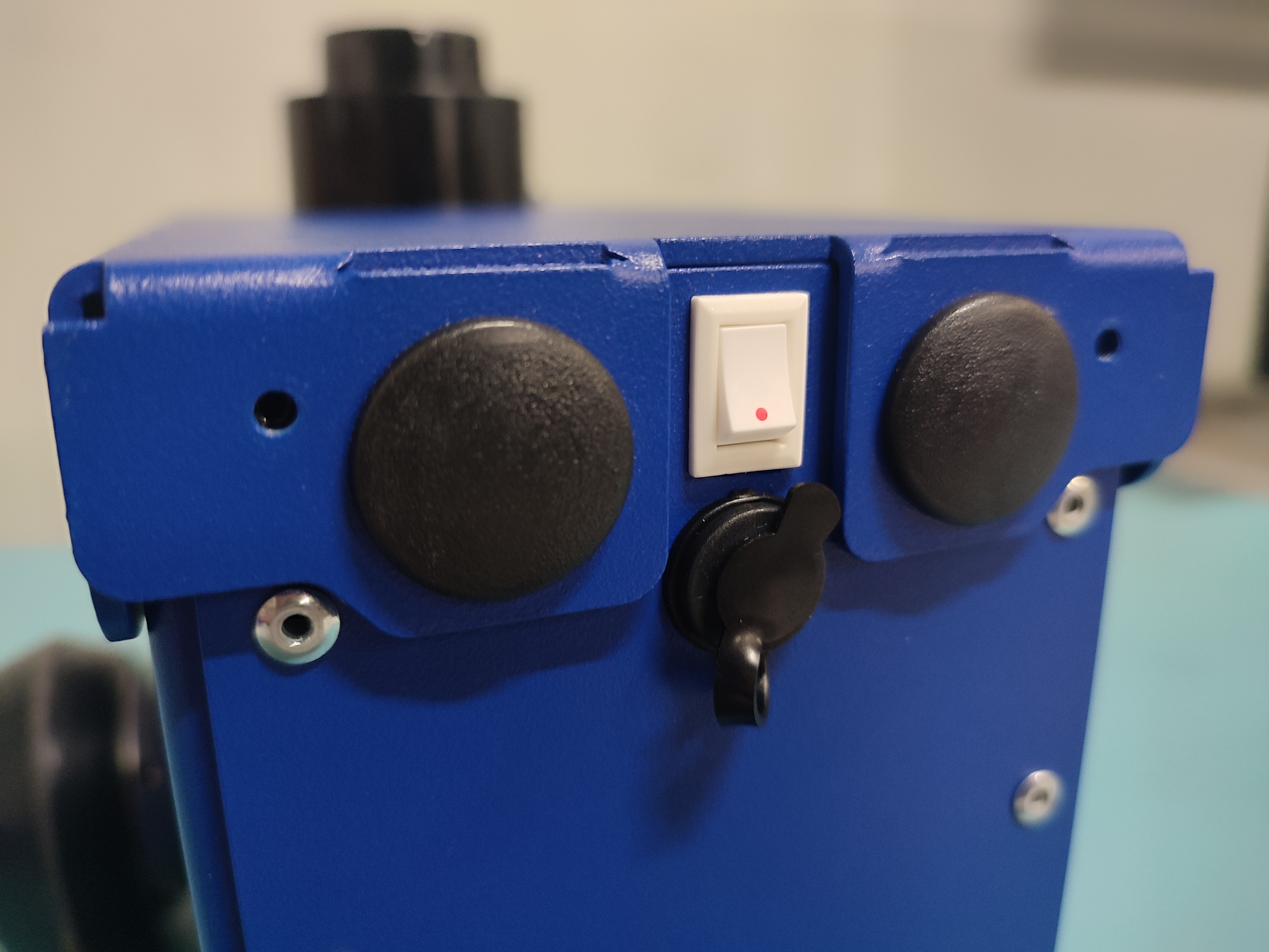
Locate the white power switch at the back of the Magni 6 Mini and turn it on.
Confirm the Raspberry Pi’s green LED is visible. This indicates the robot is powered on.
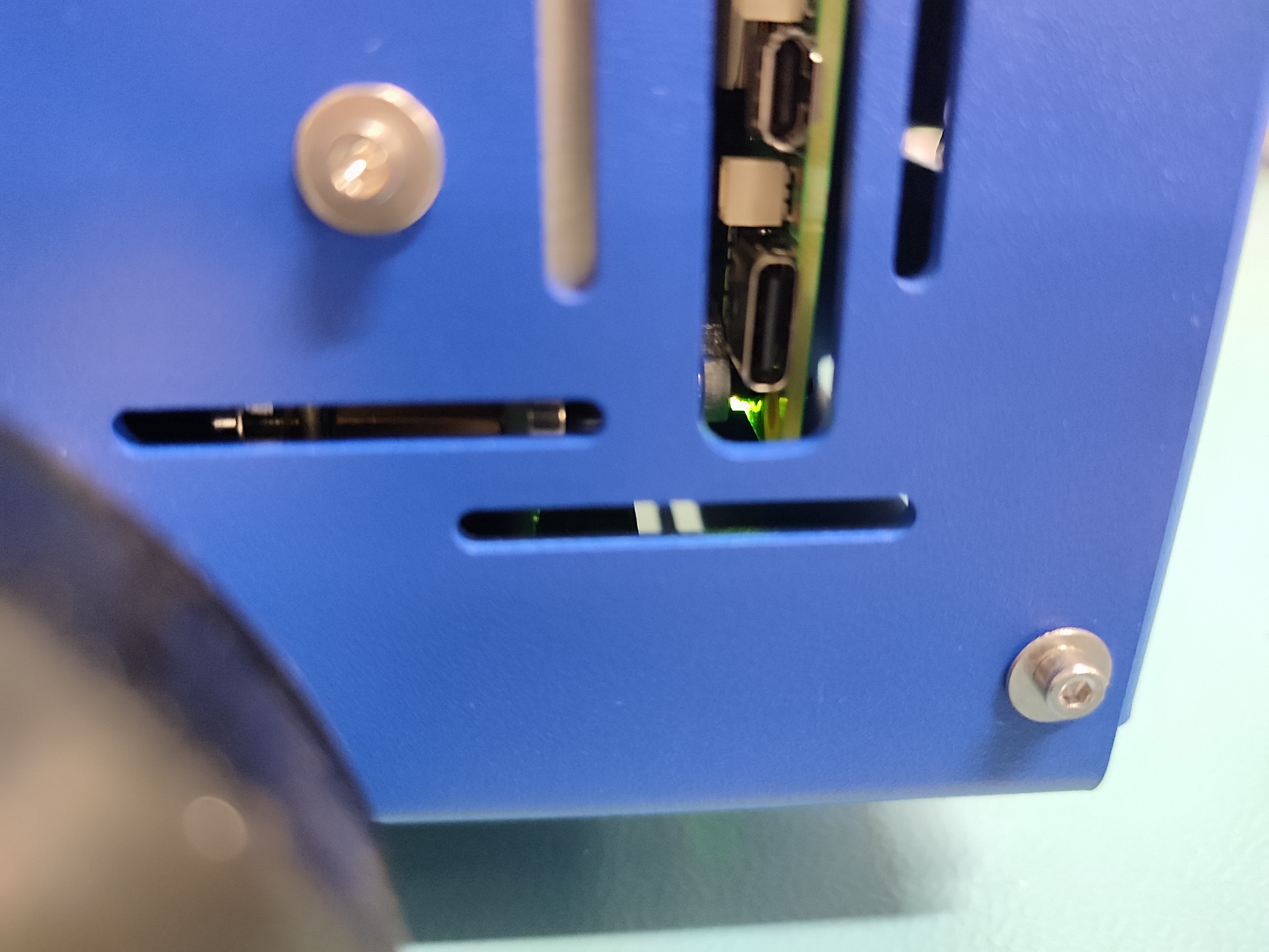
The robot is now powered on and ready for connection.
Note
If the Raspberry Pi’s light is not green, ensure all components are properly connected.
Warning
Before messing with the hardware, switch the white switch off, to turn off the power to the robot.
Next Step: Connecting
Once powered, follow Connecting to the Robot to set up the connection between your robot and workstation.